
If you need an easy-to-build and good-quality 3A power supply circuit. Many experts often recommend using LM350. It is a 3A voltage regulator IC for DC adjustable power supply(1.25V to 35V), high-performance, with a few components.
This circuit looks like My first Variable DC Power Supply. But this is more output current. So, this circuit can supply more loads. And, we can buy this IC at stores near you.
I know in your mind, now you want to build this cycle. But many times, I was impatient for not learning the components. Then causing the circuit to work poorly. I do not want you to be like me. So, we should learn it first.
LM350 datasheet
How to use LM350? Which there is a simple detail to do this:
The LM350 is best for you. Because it is the adjustable three-terminal positive voltage regulator.
Which looks like a popular LM317. We can set the output voltage with only two external resistors. But It can supply the output current over 3.0A, on the voltage range of 1.2 V to 33 V.
In addition, it uses internal current limiting, thermal shutdown, and safe mode.
We can use the LM350 on a wide variety of applications. For example A simple adjustable switching regulator, a programmable output regulator, a precision current regulator by connecting a fixed resistor between the adjust and output pins.
In short, it works like the LM317 but can supply a higher current.
LM350 Pinout
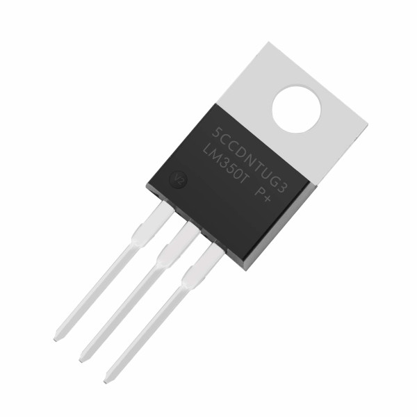
As in the LM350 pinout above. It looks much like the popular LM317. Also, its pin output connects the heatsink surface.
Buy HERE
Caution!Since it has a high current of over 3A, we must mount the LM350 on the large heatsink.
Basic Features
- 3.0 A Output Current
- Output Adjustable Voltage from 1.2 V to 33 V
- Load Regulation Typically 0.1%
- Line Regulation Typically 0.005%/V
- Internal Thermal Overload Protection
- Internal Short Circuit
- Current Limiting Constant with Temperature
- Output Transistor Safe Area Compensation
- Floating Operation for High Voltage Applications
LM350 VOLTAGE REGULATOR CALCULATOR
We love it because easy to use. You see the LM350 circuit below. We use only 2 resistors to control the output voltage. The formula is:
Vout = 1.25 x {1+(R2/R1)}
Enter R1 (Ω): Enter R2 (Ω): Calculate
In normal operation, the LM350 has a nominal 1.25V reference voltage (Vref) between the output lead and Adjustable lead (ADJ).
And, since the voltage is constant, a constant current. Then flows through the output set resistor R2. To adjust voltage output.
Using the Resistors list (No calculating)
If we do not have a calculator or busy or slow brain like me. Using the resistors list is an easy solution. Just choose the suitable resistors according to the voltage rate.
1.43V : R1 = 470Ω, R2 = 68Ω1.47V : R1 = 470Ω, R2 = 82Ω1.47V : R1 = 390Ω, R2 = 68Ω1.51V : R1 = 330Ω, R2 = 68Ω1.51V : R1 = 390Ω, R2 = 82Ω1.52V : R1 = 470Ω, R2 = 100Ω1.53V : R1 = 390Ω, R2 = 82Ω1.56V : R1 = 330Ω, R2 = 82Ω1.57V : R1 = 270Ω, R2 = 68Ω1.57V : R1 = 470Ω, R2 = 120Ω1.57V : R1 = 390Ω, R2 = 100Ω1.59V : R1 = 390Ω, R2 = 100Ω1.60V : R1 = 240Ω, R2 = 68Ω1.63V : R1 = 330Ω, R2 = 100Ω1.63V : R1 = 270Ω, R2 = 82Ω1.64V : R1 = 390Ω, R2 = 120Ω1.64V : R1 = 220Ω, R2 = 68Ω1.65V : R1 = 470Ω, R2 = 150Ω1.66V : R1 = 390Ω, R2 = 120Ω1.68V : R1 = 240Ω, R2 = 82Ω1.71V : R1 = 330Ω, R2 = 120Ω1.71V : R1 = 270Ω, R2 = 100Ω1.72V : R1 = 220Ω, R2 = 82Ω1.72V : R1 = 180Ω, R2 = 68Ω1.73V : R1 = 470Ω, R2 = 180Ω1.73V : R1 = 390Ω, R2 = 150Ω1.76V : R1 = 390Ω, R2 = 150Ω1.77V : R1 = 240Ω, R2 = 100Ω1.81V : R1 = 270Ω, R2 = 120Ω1.82V : R1 = 150Ω, R2 = 68Ω1.82V : R1 = 330Ω, R2 = 150Ω1.82V : R1 = 180Ω, R2 = 82Ω1.83V : R1 = 390Ω, R2 = 180Ω1.84V : R1 = 470Ω, R2 = 220Ω1.86V : R1 = 390Ω, R2 = 180Ω1.88V : R1 = 240Ω, R2 = 120Ω1.89V : R1 = 470Ω, R2 = 240Ω1.93V : R1 = 330Ω, R2 = 180Ω1.93V : R1 = 150Ω, R2 = 82Ω1.94V : R1 = 270Ω, R2 = 150Ω1.96V : R1 = 390Ω, R2 = 220Ω1.97V : R1 = 470Ω, R2 = 270Ω1.99V : R1 = 390Ω, R2 = 220Ω2.02V : R1 = 390Ω, R2 = 240Ω2.03V : R1 = 240Ω, R2 = 150Ω2.06V : R1 = 390Ω, R2 = 240Ω2.08V : R1 = 330Ω, R2 = 220Ω2.10V : R1 = 220Ω, R2 = 150Ω2.12V : R1 = 390Ω, R2 = 270Ω2.13V : R1 = 470Ω, R2 = 330Ω2.16V : R1 = 330Ω, R2 = 240Ω2.16V : R1 = 390Ω, R2 = 270Ω2.19V : R1 = 240Ω, R2 = 180Ω2.23V : R1 = 470Ω, R2 = 390Ω2.25V : R1 = 150Ω, R2 = 120Ω2.27V : R1 = 270Ω, R2 = 220Ω2.27V : R1 = 330Ω, R2 = 270Ω2.29V : R1 = 470Ω, R2 = 390Ω2.29V : R1 = 180Ω, R2 = 150Ω2.31V : R1 = 390Ω, R2 = 330Ω2.36V : R1 = 270Ω, R2 = 240Ω2.37V : R1 = 390Ω, R2 = 330Ω2.40V : R1 = 240Ω, R2 = 220Ω2.44V : R1 = 390Ω, R2 = 390Ω2.50V : R1 = 470Ω, R2 = 470Ω2.57V : R1 = 390Ω, R2 = 390Ω2.61V : R1 = 220Ω, R2 = 240Ω2.65V : R1 = 330Ω, R2 = 390Ω2.66V : R1 = 240Ω, R2 = 270Ω2.73V : R1 = 330Ω, R2 = 390Ω2.74V : R1 = 470Ω, R2 = 560Ω2.75V : R1 = 150Ω, R2 = 180Ω2.76V : R1 = 390Ω, R2 = 470Ω2.78V : R1 = 270Ω, R2 = 330Ω2.78V : R1 = 220Ω, R2 = 270Ω2.84V : R1 = 390Ω, R2 = 470Ω2.92V : R1 = 180Ω, R2 = 240Ω2.96V : R1 = 270Ω, R2 = 390Ω2.97V : R1 = 240Ω, R2 = 330Ω3.03V : R1 = 330Ω, R2 = 470Ω3.05V : R1 = 390Ω, R2 = 560Ω3.06V : R1 = 270Ω, R2 = 390Ω3.06V : R1 = 470Ω, R2 = 680Ω3.08V : R1 = 150Ω, R2 = 220Ω3.13V : R1 = 220Ω, R2 = 330Ω3.14V : R1 = 390Ω, R2 = 560Ω3.18V : R1 = 240Ω, R2 = 390Ω3.25V : R1 = 150Ω, R2 = 240Ω3.28V : R1 = 240Ω, R2 = 390Ω3.35V : R1 = 220Ω, R2 = 390Ω3.37V : R1 = 330Ω, R2 = 560Ω3.43V : R1 = 270Ω, R2 = 470Ω3.43V : R1 = 390Ω, R2 = 680Ω3.43V : R1 = 470Ω, R2 = 820Ω3.47V : R1 = 220Ω, R2 = 390Ω3.50V : R1 = 150Ω, R2 = 270Ω3.54V : R1 = 180Ω, R2 = 330Ω3.55V : R1 = 390Ω, R2 = 680Ω3.70V : R1 = 240Ω, R2 = 470Ω3.82V : R1 = 180Ω, R2 = 390Ω3.83V : R1 = 330Ω, R2 = 680Ω3.84V : R1 = 270Ω, R2 = 560Ω3.88V : R1 = 390Ω, R2 = 820Ω3.91V : R1 = 470Ω, R2 = 1K3.92V : R1 = 220Ω, R2 = 470Ω3.96V : R1 = 180Ω, R2 = 390Ω4.00V : R1 = 150Ω, R2 = 330Ω4.02V : R1 = 390Ω, R2 = 820Ω4.17V : R1 = 240Ω, R2 = 560Ω4.33V : R1 = 150Ω, R2 = 390Ω4.36V : R1 = 330Ω, R2 = 820Ω4.40V : R1 = 270Ω, R2 = 680Ω4.43V : R1 = 220Ω, R2 = 560Ω4.44V : R1 = 470Ω, R2 = 1.2K4.46V : R1 = 390Ω, R2 = 1K4.50V : R1 = 150Ω, R2 = 390Ω4.51V : R1 = 180Ω, R2 = 470Ω4.63V : R1 = 390Ω, R2 = 1K4.79V : R1 = 240Ω, R2 = 6805.04V : R1 = 330Ω, R2 = 1K5.05V : R1 = 270Ω, R2 = 820Ω5.10V : R1 = 390Ω, R2 = 1.2K5.11V : R1 = 220Ω, R2 = 680Ω5.14V : R1 = 180Ω, R2 = 560Ω5.17V : R1 = 150Ω, R2 = 470Ω5.24V : R1 = 470Ω, R2 = 1.5K5.30V : R1 = 390Ω, R2 = 1.2K5.52V : R1 = 240Ω, R2 = 820Ω5.80V : R1 = 330Ω, R2 = 1.2K5.88V : R1 = 270Ω, R2 = 1K5.91V : R1 = 220Ω, R2 = 820Ω5.92V : R1 = 150Ω, R2 = 560Ω5.97V : R1 = 180Ω, R2 = 680Ω6.04V : R1 = 470Ω, R2 = 1.8K6.06V : R1 = 390Ω, R2 = 1.5K6.32V : R1 = 390Ω, R2 = 1.5K6.46V : R1 = 240Ω, R2 = 1K6.81V : R1 = 270Ω, R2 = 1.2K6.92V : R1 = 150Ω, R2 = 680Ω6.93V : R1 = 330Ω, R2 = 1.5K6.94V : R1 = 180Ω, R2 = 820Ω7.02V : R1 = 390Ω, R2 = 1.8K7.10V : R1 = 470Ω, R2 = 2.2K7.33V : R1 = 390Ω, R2 = 1.8K7.50V : R1 = 240Ω, R2 = 1.2K8.07V : R1 = 330Ω, R2 = 1.8K8.08V : R1 = 150Ω, R2 = 820Ω8.19V : R1 = 270Ω, R2 = 1.5K8.30V : R1 = 390Ω, R2 = 2.2K8.43V : R1 = 470Ω, R2 = 2.7K8.68V : R1 = 390Ω, R2 = 2.2K9.06V : R1 = 240Ω, R2 = 1.5K9.58V : R1 = 330Ω, R2 = 2.2K9.77V : R1 = 220Ω, R2 = 1.5K9.90V : R1 = 390Ω, R2 = 2.7K10.03V : R1 = 470Ω, R2 = 3.3K10.37V : R1 = 390Ω, R2 = 2.7K10.63V : R1 = 240Ω, R2 = 1.8K11.25V : R1 = 150Ω, R2 = 1.2K11.44V : R1 = 270Ω, R2 = 2.2K11.48V : R1 = 330Ω, R2 = 2.7K11.67V : R1 = 180Ω, R2 = 1.5K11.83V : R1 = 390Ω, R2 = 3.3K12.40V : R1 = 390Ω, R2 = 3.3K12.71V : R1 = 240Ω, R2 = 2.2K13.75V : R1 = 330Ω, R2 = 3.3K15.31V : R1 = 240Ω, R2 = 2.7K16.25V : R1 = 150Ω, R2 = 1.8K16.53V : R1 = 270Ω, R2 = 3.3K16.59V : R1 = 220Ω, R2 = 2.7K18.44V : R1 = 240Ω, R2 = 3.3K19.58V : R1 = 150Ω, R2 = 2.2K20.00V : R1 = 220Ω, R2 = 3.3K23.75V : R1 = 150Ω, R2 = 2.7K24.17V : R1 = 180Ω, R2 = 3.3K28.75V : R1 = 150Ω, R2 = 3.3K
Table R1 and R2
For example, you need a 5V 3A power supply. You look at 5.00V. We can see at 5.04V or 5.05V rate.I look at 5.05V because I have R1=270 ohms. Then I use R2 is 820 ohms. Is it easy?
Capacitors filter
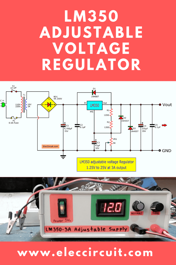
- Both C1 and C4-0.1uF are input bypass capacitors. It needs if devices (IC1) more than 6 inches from filter capacitors.
- C3-47uF is a bypass capacitor that prevents 86dB ripple rejection.
- C4- 100uF is used to improves transient response. Output capacitor in the range of 1uF to 1000uF of tantalum electrolytic. It is commonly used to provide improved output impedance and rejection of transients.
Protection Diodes
When external capacitors are used with any IC regulators. Sometimes necessary to add a protection diode to prevent the capacitors from discharging through a low current point into the regulator.
Although the surge is short, there is enough energy to damage parts of the IC.
- When negative voltage or 20A spikes flow backward the output will be absorbed voltage with D3-diode.
- Then D2 to protect Out and Adj lead.
- D1 is protected voltage spikes to Input and output lead.
Note: D1-D3 are 1N4007 diodes.
Learn more: 0-30V 0-5A regulated variable power supply12V to 5V converter step down
What is more? let’s build the circuit.
How LM350 regulator works
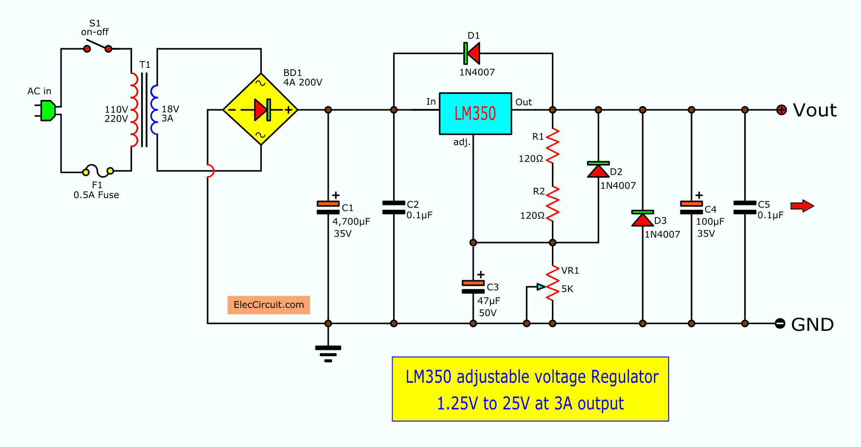
In the figure below, the circuit is similar to my first variable DC power supply.
When we apply AC220V or AC110V(for the USA) by pressing S1 to turn on this power supply. The ACV will flow through F1 for protection when the overload or too much voltage input.
Then, the ACV will pass into a transformer that has the ability to transform a high AC voltage to lower levels of AC-18V, and it comes to BD1-bridge diode to convert(rectifier) AC to DC.
Next, they will through C1-4700uF electrolytic capacitor to smooth (filter) the pulsating voltage from a transformer into a steady direct current (DC).
Now we have voltage at this point is 22V to 25V
And then, the current will via to the input pin of the IC1-LM350. As I said above.
It is a 3A adjustable regulator IC. The output regulated voltage can be controlled of 1.2V to 22V by rotating VR1.
Read also: Microcontroller | Digital power supply circuit
Make LM350 power supply
First of all, get any parts by the list below.
Components list
IC1: LM350T 3 terminal positive voltage regulator 3AmpBuy now. I think it is interesting maybe it is right for you.C1: 4700uF 35V, ElectrolyticC3: 47uF 35V, ElectrolyticC5: 100uF 50V, ElectrolyticC6: 1000uF 16V, ElectrolyticC2,C4: 0.1uF 50V, Ceramic or Mylar capacitorsC7: 0.01uF 50V, CeramicBD1: 4A 200V bridge diodeD1-D3: 1N4007, 1A 1000V DiodeR1,R2: 120Ω 0.5W resistorsVR1: Variable Resistors 5K(B)S1: On-Off or SPST switchF1, 0.5A-1A FuseT1, 3A 18V to 21V secondary transformerHeatsink, Perforated PCB, Wires, DC Fan, LED voltmeter, and others
Assembling the Circuit
The circuit has a few parts, so I assemble devices on a perforated PCB.
I like to use it. Because we can build prototypes very quickly and save them as well
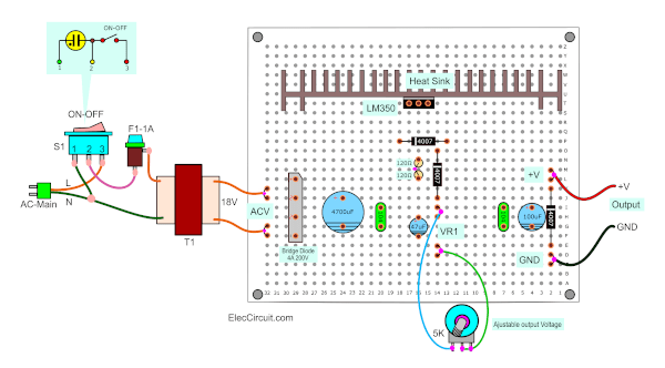
Look at the components layout below.
 And the wiring of each soldering point of device pins.
See the LM350 regulator prototypes
Remember: Using the perforated PCB. We should increase the size of the copper wire in the high-current circuit, such as Ground, Input, Output of IC. You may be added a lead solder to make the circuit line larger. As below.
We need to mount the LM350 with a big heatsink. Because while it runs, is very hot.
It looks like a TO-220 transistor so we mount it the same. Be careful it short circuit to a heatsink case.
I like to make electronics with economical method. We can build a good project. For example, using the device legs as wiring connection points on the PCB.
See below, when I assemble 1N4007 Diode. I use its leg into the wiring connection on PCB.
About transformer
The voltage level of the secondary winding of the transformer affects the maximum output voltage level. In this circuit, I need an output voltage of about 22V. So I use a secondary coil of 18V.
But if you don’t have such a voltage rating. You may use an 18V CT 18V transformer. But only use 18V and CT are used. The rest are not used. To see the illustrations.
Or use a 9V CT 9V transformer, but not using CT.
If you use a 20V transformer, the output will be 25V max. Do not should over-voltage more than 24V. The IC may not run cool.
Another issue is the ON-OFF switch S1 with a built-in lamp or Neon lamp. We will connect the circuit as shown. Of course, we have to clearly define L and N.
💡 Need more learning? Try all these basic components with images.
Remember: Check the switch with a meter for sure before connect to AC main. It is dangerous high voltage!
Testing
To begin with, check the circuit and wiring for error. Then, adjust VR1 to a minimum. Next, we test this project with apply voltage output is 1.2V.
Then, adjust the voltage to 12V. And next, I try to use the 12V 50W lamp as the load. The voltage will must not lower than 12V and I measure the current of the lamp is 3.5A.
You can watch the video below.
This project is good as I need to. I am happy. Thank you for watching.
Increasing Performance
Also, we can increase the performance of this project as follows.
- Adding a potentiometer for fine adjusting like an LM317 power supply.
- Adding LED voltmeter to read easily a voltage level.
It requires a source as a DC power supply. My transformer has another secondary coil. I apply this. See the circuit below.
This is a simple DC unregulated power supply circuit. The AC 6V is rectified with D4-D7 and filtered with C6, C7 to DC 8V for the LED voltmeter and the DC fan.
- Add a cooling fan. While it is running. It is so hot. We should add a cooling fan(12V) to close the heatsink.
Then, We assembled this project on the ABS Plastic Electronic Project Junction Box in Enclosure Case.
Because the drill is easy to install as an electrical insulator And cheap too.
Front of the prototype
Look at! We finished the LM350 adjustable voltage Regulator project.
…
Download This
All full-size images of this post are in this Ebook: Elec Circuit vol. 2 below. Please support me.
We recommend other circuits using LM350
12V to 6A 3A DC converter—you can reduce 12V to 6V for any the circuit. Using 6V regulator.
24V 3A Regulator—We love it, and you?
0-12V 3A Variable Power Supply
If you want test small load at high current. Try this circuit! it can start voltage at zero voltage with LM350. And can protect load of wrong polarity. ✅ Learn how to design and build it → 0-12V Power Supply at 3A
High power pulse generator up to 3A max—It may control the Motor or lamp with a pulse. Low current use! It is good learning too.
OR…What is more? it is not enough!Look: LM338 Adjustable Power Supply 5A and 10A